Of all the tests employed for used oil analysis, none provides better test repeatability or consistency than viscosity. Likewise, there is no property more critical to effective component lubrication than base oil viscosity. However, there is more to viscosity than meets the eye. Viscosity can be measured and reported as dynamic (absolute) viscosity or as kinematic viscosity. The two are easily confused, but are significantly different.
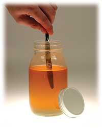 Which fluid is more viscous, honey or mayonnaise? If you said mayonnaise, you are correct … at least partially. Likewise, if you said honey you are partially correct. The reason for the apparent anomaly is that when rotating the knife in both substances, the shear rate varies, while turning each jar on its side is simply measuring the static resistance to flow. Because honey is a Newtonian fluid while mayonnaise is non-Newtonian, the viscosity of the mayonnaise drops as the shear rate increases, or as the knife is rotated. Stirring subjects the mayonnaise to a high shear stress, causing it to yield to the forcing action. Conversely, simply setting the jar on its side subjects the mayonnaise to a low shear stress, resulting in little to no viscosity change, so it tends to stay in the jar.
Most used oil analysis laboratories measure and report kinematic viscosity. By contrast, most onsite viscometers measure absolute viscosity, but are typically programmed to estimate and report kinematic viscosity, so that the viscosity measurements reported reflect kinematic numbers reported by most labs and lube oil suppliers. Given the importance of viscosity analysis coupled with the increasing popularity of onsite oil analysis instruments used to screen and supplement offsite laboratory oil analysis, it is essential that oil analysts clearly understand the difference between absolute and kinematic viscosity measurements.
Generally speaking, viscosity is a fluid’s resistance to flow (shear stress) at a given temperature. Sometimes, viscosity is erroneously referred to as thickness (or weight). Viscosity is not a dimensional measurement, so calling highly viscous oil thick and less viscous oil thin is misleading. Likewise, reporting viscosity for trending purposes without a reference to temperature is nonsensical. The temperature must be defined to interpret the viscosity reading. Typically, viscosity is reported at 40°C and/or 100°C or both if the viscosity index is required.
Measuring Viscosity
Several engineering units are used to express viscosity, but the most common by far are centistoke (cSt) for kinematic viscosity and the centipoise (cP) for dynamic (absolute) viscosity. The kinematic viscosity in cSt at 40°C is the basis for the ISO 3448 kinematic viscosity grading system, making it the international standard. Other common kinematic viscosity systems such as Saybolt Universal Seconds (SUS) and the SAE grading system can be related to the measurement of the viscosity in cSt at either 40°C or 100°C.
Several engineering units are used to express viscosity, but the most common by far are centistoke (cSt) for kinematic viscosity and the centipoise (cP) for dynamic (absolute) viscosity. The kinematic viscosity in cSt at 40°C is the basis for the ISO 3448 kinematic viscosity grading system, making it the international standard. Other common kinematic viscosity systems such as Saybolt Universal Seconds (SUS) and the SAE grading system can be related to the measurement of the viscosity in cSt at either 40°C or 100°C.
Kinematic viscosity is traditionally measured by noting the time it takes oil to travel through the orifice of a capillary under the force of gravity (Figure 1). The orifice of the kinematic viscometer tube produces a fixed resistance to flow. Different sized capillaries are available to support fluids of varying viscosity. The time taken for the fluid to flow through the capillary tube can be converted directly to a kinematic viscosity using a simple calibration constant provided for each tube. The dominant procedure for performing kinematic viscosity measurements is ASTM D445, often modified in the used oil analysis lab to save time and make the test measurement more efficient.
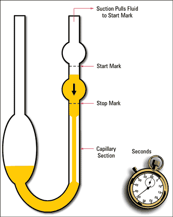 |
Figure 1. Capillary U-Tube Viscometer
|
Absolute viscosity is measured as the resistance to flow when an external and controlled force (pump, pressurized air, etc.) forces oil through a capillary (ASTM D4624), or a body is forced through the fluid by an external and controlled force such as a spindle driven by a motor. In either case, the resistance to flow (or shear) as a function of the input force is measured, which reflects the internal resistance of the sample to the applied force, or its dynamic viscosity.
There are several types and embodiments of absolute viscometers. The Brookfield rotary method pictured in Figure 2 is the most common. Absolute viscosity measurement has historically been used for research applications, quality control and grease analysis within the field of machinery lubrication.
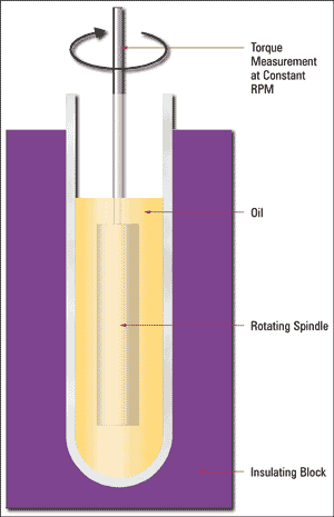 |
Figure 2. Rotary Viscometer ASTM D2983
|
Procedures for testing absolute viscosity in the lab by the traditional Brookfield method are defined by ASTM D2983, D6080 and others. However, absolute viscosity is becoming increasingly common in the area of used oil analysis because most onsite viscometers sold on the market today measure absolute viscosity, not kinematic viscosity. Suppliers of onsite absolute viscometers are Cambridge, Kittiwake, CSI, Spectro and Entek.
Generally speaking, kinematic viscosity (cSt) is related to absolute viscosity (cP) as a function of the fluid’s specific gravity (SG) according to the equations in figure 3.
 |
Figure 3. Viscosity Equations
|
As simple and elegant as these equations look, they hold true only for so-called Newtonian fluids. In addition, the specific gravity of the fluid must remain constant during the trending period. Neither of these conditions can be assumed constant in used oil analysis, so the analyst must be aware of the conditions under which variance can occur.
Newtonian vs. Non-Newtonian Fluids
A Newtonian fluid can be described as a fluid that maintains constant viscosity across all shear rates (shear stress varies linearly with shear rate). These fluids are called Newtonian because they follow the original formula established by Sir Isaac Newton in his Law of Fluid Mechanics. Some fluids, however, don’t behave this way. In general, they are called non-Newtonian fluids. A group of non-Newtonian fluids referred to as thixotropic are of particular interest in used oil analysis because the viscosity of a thixotropic fluid decreases as the shear rate increases. The viscosity of a thixotropic fluid increases as shear rate decreases. With thixotropic fluids, set-time can increase apparent viscosity as in the case of grease.
A Newtonian fluid can be described as a fluid that maintains constant viscosity across all shear rates (shear stress varies linearly with shear rate). These fluids are called Newtonian because they follow the original formula established by Sir Isaac Newton in his Law of Fluid Mechanics. Some fluids, however, don’t behave this way. In general, they are called non-Newtonian fluids. A group of non-Newtonian fluids referred to as thixotropic are of particular interest in used oil analysis because the viscosity of a thixotropic fluid decreases as the shear rate increases. The viscosity of a thixotropic fluid increases as shear rate decreases. With thixotropic fluids, set-time can increase apparent viscosity as in the case of grease.
A Practical Example 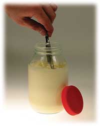 Imagine you have two jars before you - one filled with mayonnaise, the other filled with honey. Assuming that both jars are affixed to the table’s surface with Velcro, imagine yourself dipping identical butter knives into each of the fluids at the same angle and to the same depth. Imagine stirring the two fluids by turning the knives at the same rpm while keeping the same angle of attack. Which of the two fluids was harder to stir? Your answer should be honey, which is a lot harder to stir than mayonnaise. Now imagine detaching the jars from the Velcro on the table and turning the jars on their side. Which flows out of the jar faster, honey or mayonnaise? Your answer should be honey; the mayonnaise probably won’t flow at all by simply turning the jar on its side.
 Imagine you have two jars before you - one filled with mayonnaise, the other filled with honey. Assuming that both jars are affixed to the table’s surface with Velcro, imagine yourself dipping identical butter knives into each of the fluids at the same angle and to the same depth. Imagine stirring the two fluids by turning the knives at the same rpm while keeping the same angle of attack. Which of the two fluids was harder to stir? Your answer should be honey, which is a lot harder to stir than mayonnaise. Now imagine detaching the jars from the Velcro on the table and turning the jars on their side. Which flows out of the jar faster, honey or mayonnaise? Your answer should be honey; the mayonnaise probably won’t flow at all by simply turning the jar on its side.
 Which fluid is more viscous, honey or mayonnaise? If you said mayonnaise, you are correct … at least partially. Likewise, if you said honey you are partially correct. The reason for the apparent anomaly is that when rotating the knife in both substances, the shear rate varies, while turning each jar on its side is simply measuring the static resistance to flow. Because honey is a Newtonian fluid while mayonnaise is non-Newtonian, the viscosity of the mayonnaise drops as the shear rate increases, or as the knife is rotated. Stirring subjects the mayonnaise to a high shear stress, causing it to yield to the forcing action. Conversely, simply setting the jar on its side subjects the mayonnaise to a low shear stress, resulting in little to no viscosity change, so it tends to stay in the jar.
One cannot conventionally measure the viscosity of a non-Newtonian fluid. Rather, one must measure the apparent viscosity, which takes into consideration the shear rate at which the viscosity measurement was made. (See Figure 4) Much like viscosity measurements don’t make sense unless the test temperature is reported, apparent viscosity measurements don’t make sense unless the test temperature and the shear rate are reported. For example, the viscosity of grease is never reported, rather the grease’s apparent viscosity is reported in centipoises (cP). (Note: the viscosity may be reported for the base oil used to make the grease, but not of the finished product.)
Generally speaking, a fluid is non-Newtonian if it is comprised of one substance suspended (but not chemically dissolved) in a host fluid. For this to happen, there are two basic categories, emulsions and colloidal suspensions. An emulsion is the stable physical coexistence of two immiscible fluids. Mayonnaise is a common non-Newtonian fluid, comprised of eggs emulsified into oil, the host fluid. Because mayonnaise is non-Newtonian, its viscosity yields with applied force, making it easy to spread.
A colloidal suspension is comprised of solid particles stably suspended in a host fluid. Many paints are colloidal suspension. If the paint was Newtonian it would either spread easily but run if the viscosity is low, or spread with great difficulty and leave brush marks, but not run if the viscosity is high. Because the paint is non-Newtonian, its viscosity yields under the force of the brush, but returns when the brush is taken away. As a result, paint spreads with relative ease, but doesn’t leave brush marks and doesn’t run.
Making the Connection
The absolute viscosity determines the film thickness provided by the oil. Kinematic viscosity is merely a convenient attempt to estimate the degree of film thickness the oil can provide, but has less significance if the oil is non-Newtonian.
The absolute viscosity determines the film thickness provided by the oil. Kinematic viscosity is merely a convenient attempt to estimate the degree of film thickness the oil can provide, but has less significance if the oil is non-Newtonian.

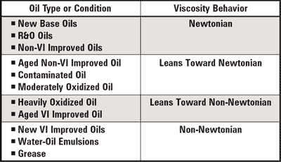
Numerous commonly encountered lubricant formulations and conditions will produce a non-Newtonian fluid, including:
• Viscosity Index (VI) Improver Additives - Multigrade mineral-based engine oils (except naturally high VI base oils) are formulated with a springy additive that is compact at low temperatures and expands at high temperatures in response to increasing fluid solvency. Because this additive molecule is different from the host oil’s molecules, it behaves in a non-Newtonian fashion.
• Water Contamination - Oil and free water don’t mix, not chemically anyway. But under certain circumstances, they will combine to form an emulsion, much like the mayonnaise discussed earlier. Anyone who has seen oil that looks like coffee with cream can attest to this fact. While it may seem counterintuitive, water contamination, when emulsified into the oil, actually increases the kinematic viscosity.
• Thermal and Oxidative Degradation By-products - Many thermal and oxidative degradation by-products are insoluble, but are carried by the oil in a stable suspension. These suspensions create non-Newtonian behavior.
• Soot - Commonly encountered in diesel engines, soot is a particle that results in a colloidal suspension in the oil. The oil’s dispersant additive, designed to keep soot particles from agglomerating and growing serves to facilitate the formation of a colloidal suspension.
If one were to measure the absolute viscosity of one of these commonly encountered emulsions or colloids described above with a variable shear rate absolute viscometer (for example, ASTM D4741), the measurement would decrease as the shear rate increases, up to a point of stabilization. If one were to divide this stabilized absolute viscosity by the specific gravity of the fluid to estimate the kinematic viscosity, the calculated value would differ from the measured kinematic viscosity. Again, the equations in Figure 3 apply to Newtonian fluids only, not non-Newtonian fluids described above, which is why this discrepancy occurs.
Specific Gravity Effects
Look at the equations in Figure 3 again. The absolute and kinematic viscosities of a Newtonian fluid are related as a function of the fluid’s specific gravity. Consider the apparatus in Figure 1, the bulb that contains the sample oil, which is released when the vacuum is eliminated, then produces a head of pressure that drives the oil through the capillary tube. Can one assume that all fluids will produce the same head of pressure? No, the pressure is a function of the fluid’s specific gravity, or weight relative to the weight of an identical volume of water. Most hydrocarbon-based lubricating oils typically have a specific gravity of 0.85 to 0.90. However, this can change over time as the oil degrades or becomes contaminated (glycol, water and wear metals for example), which produces a differential between absolute and kinematic viscosity measurements.
Look at the equations in Figure 3 again. The absolute and kinematic viscosities of a Newtonian fluid are related as a function of the fluid’s specific gravity. Consider the apparatus in Figure 1, the bulb that contains the sample oil, which is released when the vacuum is eliminated, then produces a head of pressure that drives the oil through the capillary tube. Can one assume that all fluids will produce the same head of pressure? No, the pressure is a function of the fluid’s specific gravity, or weight relative to the weight of an identical volume of water. Most hydrocarbon-based lubricating oils typically have a specific gravity of 0.85 to 0.90. However, this can change over time as the oil degrades or becomes contaminated (glycol, water and wear metals for example), which produces a differential between absolute and kinematic viscosity measurements.
Consider the data presented in Table 2. Each of the new oil scenarios is identical, and in both instances the absolute viscosity increases by 10 percent, usually the condemning limit for a change in viscosity. In scenario A, the modest change in specific gravity results in a slight differential between measured absolute viscosity and kinematic viscosity. This differential could slightly delay the sounding of the oil change alarm, but wouldn’t cause much of an error. However, in scenario B, the differential is much greater. Here, the specific gravity increases significantly, which results in a measured increase of 1.5 percent in kinematic viscosity, versus a 10 percent increase as measured with an absolute viscometer. This is a significant difference that could lead the analyst to identify the situation as nonreportable. The error that has been made is the assumption in both scenarios that the fluids remain Newtonian.
Due to the many possibilities of forming non-Newtonian fluids, the true parameter of interest for the oil analyst and lube tech should be absolute viscosity. It is what determines the fluid’s film thickness and the degree to which component surfaces are protected. In the interest of economy, simplicity and the fact that new lubricant test procedures are commonly borrowed for used oil analysis, the kinematic viscosity of the oil is typically the measured parameter used for trending and making lube management decisions. However, in certain cases this may be introducing needless errors in determining the viscosity of an oil.
The problem can be reduced to simple mathematics. As the equations in Figure 3 suggest, the absolute and kinematic viscosity are related as a function of the oil’s specific gravity. If both the viscosity and specific gravity are dynamic, but only one is measured, an error will occur, and the kinematic viscosity will not provide an accurate assessment of the change in the fluid’s absolute viscosity, the parameter of interest. The amount of error is a function of the amount of change in the unmeasured parameter, the specific gravity.
Important Conclusions
One can draw the following conclusions from this discussion about viscosity measurement:
One can draw the following conclusions from this discussion about viscosity measurement:
• Assuming the lab measures viscosity by kinematic methods, adding specific gravity measurement to a routine laboratory oil analysis program will help to eliminate this as a variable in estimating absolute viscosity from the measured kinematic viscosity.
• When using an onsite viscometer, don’t look for complete agreement between the laboratory’s kinematic viscometer and the onsite instrument. Most of these devices measure absolute viscosity (cP) and apply an algorithm to estimate the kinematic viscosity (cSt), often holding the specific gravity constant. Consider trending the results from the onsite viscometer in cP. It is the parameter being measured, and it helps to differentiate the onsite trend from the trend of data produced by the laboratory with a kinematic viscometer. Don’t try to achieve perfect agreement between the onsite and laboratory-based viscosity measurements. It is futile and generates little value. At best, look for loose correlation. Always baseline the new oil with the same viscometer you are using with the in-service oil.
• Recognize that non-Newtonian fluids don’t provide the same film protection for a given kinematic viscosity as a Newtonian fluid of the same kinematic viscosity. Because the viscosity of a non-Newtonian fluid will vary with the shear rate, the film’s strength is weakened under operating load and speed. That is one of the reasons that emulsified water increases the rate of wear in components such as rolling element bearings, where fluid film strength is critical (of course, water also causes other wear mechanisms like vaporous cavitation, rust and hydrogen embrittlement and blistering).
Viscosity is a critical fluid property, and viscosity monitoring is essential to oil analysis. Absolute and kinematic viscosity measurement techniques can produce very different results when testing used oils. Be sure the ins and outs of viscosity measurement and viscous fluid behavior are understood so accurate lubrication decisions can be made.

Thickness 1.10.3.1763 Crack is the best apparatus for such positions, which is basic in any event, for fledglings. Besides, it is a profoundly reliable programming for little and medium-sized firms and organizations
ReplyDeleteOur products, such as hydraulic oils UAE for high-pressure systems and transformer oil for electrical applications, are engineered to meet international standards, ensuring reliability and efficiency.
ReplyDelete